
With this activity my goal was to evaluate how straight lines robot can go and to enable me to “see” robot movement I was tracking LED light with camera long exposure shoot. To make photograph clean with no positioning movements captured, I had to control LED when it is turned on and off. One very useful software for this task was RoboDK which allows to program robot and simulate all axis movements. This software is simple, easy to uses and it has nice 30 day trail period.
Controlling LED
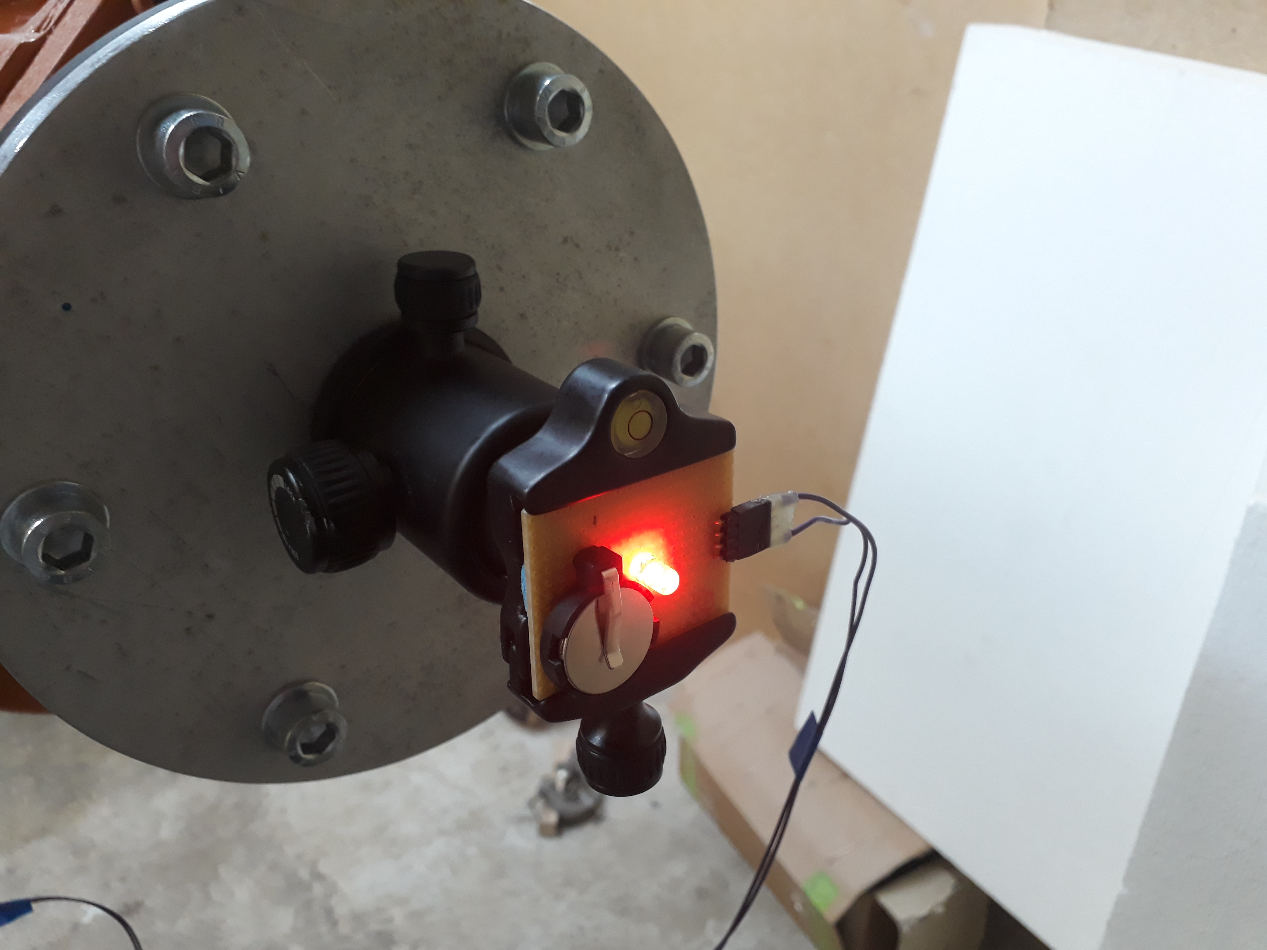
My KUKA KRC2 controller is equipped with digital I/O interface card and it’s output was used to drive relay that turned on and off the LED light. Below you can see a prototype board that was made and fixture where LED was attached. These two wires that you are seeing that are connected to the board are connected to relay that is driven by KUKA controllers Output. It is a simple command in robot code that sets particular output to needed level high or low, which then latches relay contact and toggles LED light.
Movement generation
For movement generation and simulations I was using RoboDK software. This application is intuitive and fairly easy to use. I had a drawing of circle and square pattern that I wanted to have and with RoboDK I was able to generate G-code, that you can see in image below. After simulations and fixing robot singularities code could be exported to robot controller. One thing that I had to add manually in robot code was setting controller output high and low to drive LED.

Movements captured
When code was loaded in controller I ran it through several times in test mode to make sure it is safe and it does not have singularities and axis are not exceeding speed limits. I had to return back to RoboDK several times to change tool orientation in order to avoid extensive axis speeds and eventually I had a code that I was able to launch on full speed
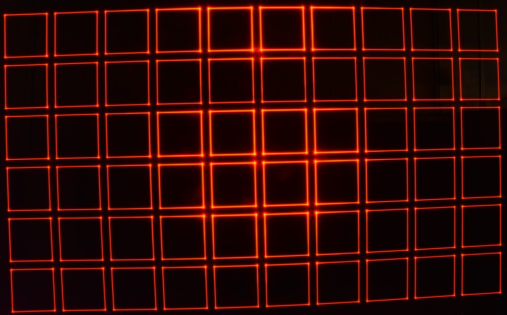
I was glad to see that lines were clean, parallel and there were no vibrations or pulsations on movement path. In images you can see distortion due to wide angle lens used and camera placement, but it gives needed information anyway.

Sources
- RoboDK software – https://robodk.com/
